ELECTRICAL ENERGY, POWER
`color{blue} ✍️` Consider a conductor with end points `A` and `B`, in which a current `I` is flowing from `A` to `B`. The electric potential at `A` and `B` are denoted by `V(A)` and `V(B)` respectively.
`color{blue} ✍️` Since current is flowing from A to B, `V(A) > V(B)` and the potential difference across AB is `color{purple}(V = V(A) – V(B) > 0.)`
`color{blue} ✍️` In a time interval `Δt`, an amount of charge `ΔQ = I Δt` travels from `A` to `B`.
`color{blue} ✍️` The potential energy of the charge at `A`, by definition, was `Q V(A)` and similarly at `B`, it is `Q V(B)`. Thus, change in its potential energy `ΔU_(pot)` is
`color{purple}(ΔU_(pot) =)` Final potential energy – Initial potential energy
`color{purple}(= ΔQ[(V (B) – V (A)] = –ΔQ V)`
`color{blue} ✍️` If charges moved without collisions through the conductor, their kinetic energy would also change so that the total energy is unchanged. Conservation of total energy would then imply that,
that is,
`color{blue} ✍️` Thus, in case charges were moving freely through the conductor under the action of electric field, their kinetic energy would increase as they move.
`color{blue} ✍️` We have, however, seen earlier that on the average, charge carriers do not move with acceleration but with a steady drift velocity.
`color{blue} ✍️` This is because of the collisions with ions and atoms during transit. During collisions, the energy gained by the charges thus is shared with the atoms.
`color{blue} ✍️` The atoms vibrate more vigorously, i.e., the conductor heats up. Thus, in an actual conductor, an amount of energy dissipated as heat in the conductor during the time interval `Δt` is,
`color{blue} ✍️` The energy dissipated per unit time is the power dissipated `color{purple}(P = (ΔW)/(Δt))` and we have,
Using Ohm’s law `V = IR`, we get
as the power loss (“ohmic loss”) in a conductor of resistance `R` carrying a current `I.`
`color{blue} ✍️` It is this power which heats up, for example, the coil of an electric bulb to incandescence, radiating out heat and light.
`color{blue} ✍️` As we have reasoned before, we need an external source to keep a steady current through the conductor. It is clearly this source which must supply this power.
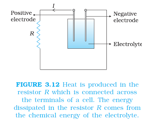
`color{blue} ✍️` In the simple circuit shown with a cell (Fig.3.12), it is the chemical energy of the cell which supplies this power for as long as it can.
`color{blue} ✍️` The expressions for power, Eqs. (3.32) and (3.33), show the dependence of the power dissipated in a resistor R on the current through it and the voltage across it. Equation (3.33) has an important application to power transmission.
`color{blue} ✍️` Electrical power is transmitted from power stations to homes and factories, which may be hundreds of miles away, via transmission cables. One obviously wants to minimise the power loss in the transmission cables connecting the power stations to homes and factories. We shall see now how this can be achieved.
`color{blue} ✍️` Consider a device `R,` to which a power `P` is to be delivered via transmission cables having a resistance `R_c` to be dissipated by it finally. If `V` is the voltage across `R` and `I` the current through it, then
`color{blue} ✍️` The connecting wires from the power station to the device has a finite resistance `R_c.` The power dissipated in the connecting wires, which is wasted is `P_c` with
`color{purple}(P_C = I^2R_c)`
`color{blue} ✍️` from Eq. (3.32), Thus, to drive a device of power P, the power wasted in the connecting wires is inversely proportional to `V^2.`
`color{blue} ✍️` The transmission cables from power stations are hundreds of miles long and their resistance `R_c` is considerable. To reduce `P_c`, these wires carry current at enormous values of `V` and this is the reason for the high voltage danger signs on transmission lines — a common sight as we move away from populated areas.
`color{blue} ✍️` Using electricity at such voltages is not safe and hence at the other end, a device called a transformer lowers the voltage to a value suitable for use.
`color{blue} ✍️` Since current is flowing from A to B, `V(A) > V(B)` and the potential difference across AB is `color{purple}(V = V(A) – V(B) > 0.)`
`color{blue} ✍️` In a time interval `Δt`, an amount of charge `ΔQ = I Δt` travels from `A` to `B`.
`color{blue} ✍️` The potential energy of the charge at `A`, by definition, was `Q V(A)` and similarly at `B`, it is `Q V(B)`. Thus, change in its potential energy `ΔU_(pot)` is
`color{purple}(ΔU_(pot) =)` Final potential energy – Initial potential energy
`color{purple}(= ΔQ[(V (B) – V (A)] = –ΔQ V)`
`color{purple}(= –I VΔt < 0)`
........(3.28)`color{blue} ✍️` If charges moved without collisions through the conductor, their kinetic energy would also change so that the total energy is unchanged. Conservation of total energy would then imply that,
`color{purple}(ΔK = –ΔU_(pot))`
........(3.29)that is,
`color{purple}(ΔK = I VΔt > 0)`
........(3.30)`color{blue} ✍️` Thus, in case charges were moving freely through the conductor under the action of electric field, their kinetic energy would increase as they move.
`color{blue} ✍️` We have, however, seen earlier that on the average, charge carriers do not move with acceleration but with a steady drift velocity.
`color{blue} ✍️` This is because of the collisions with ions and atoms during transit. During collisions, the energy gained by the charges thus is shared with the atoms.
`color{blue} ✍️` The atoms vibrate more vigorously, i.e., the conductor heats up. Thus, in an actual conductor, an amount of energy dissipated as heat in the conductor during the time interval `Δt` is,
`color{purple}(ΔW = I VΔt)`
........(3.31)`color{blue} ✍️` The energy dissipated per unit time is the power dissipated `color{purple}(P = (ΔW)/(Δt))` and we have,
`color{purple}(P = I V)`
........(3.32)Using Ohm’s law `V = IR`, we get
`color{purple}(P = I^2 R = V^2/R)`
........(3.33)as the power loss (“ohmic loss”) in a conductor of resistance `R` carrying a current `I.`
`color{blue} ✍️` It is this power which heats up, for example, the coil of an electric bulb to incandescence, radiating out heat and light.
`color{blue} ✍️` As we have reasoned before, we need an external source to keep a steady current through the conductor. It is clearly this source which must supply this power.
`color{blue} ✍️` In the simple circuit shown with a cell (Fig.3.12), it is the chemical energy of the cell which supplies this power for as long as it can.
`color{blue} ✍️` The expressions for power, Eqs. (3.32) and (3.33), show the dependence of the power dissipated in a resistor R on the current through it and the voltage across it. Equation (3.33) has an important application to power transmission.
`color{blue} ✍️` Electrical power is transmitted from power stations to homes and factories, which may be hundreds of miles away, via transmission cables. One obviously wants to minimise the power loss in the transmission cables connecting the power stations to homes and factories. We shall see now how this can be achieved.
`color{blue} ✍️` Consider a device `R,` to which a power `P` is to be delivered via transmission cables having a resistance `R_c` to be dissipated by it finally. If `V` is the voltage across `R` and `I` the current through it, then
`color{purple}(P = VI)`
........(3.34)`color{blue} ✍️` The connecting wires from the power station to the device has a finite resistance `R_c.` The power dissipated in the connecting wires, which is wasted is `P_c` with
`color{purple}(P_C = I^2R_c)`
`color{purple}(=(P^2R_C)/V^2)`
........(3.35)`color{blue} ✍️` from Eq. (3.32), Thus, to drive a device of power P, the power wasted in the connecting wires is inversely proportional to `V^2.`
`color{blue} ✍️` The transmission cables from power stations are hundreds of miles long and their resistance `R_c` is considerable. To reduce `P_c`, these wires carry current at enormous values of `V` and this is the reason for the high voltage danger signs on transmission lines — a common sight as we move away from populated areas.
`color{blue} ✍️` Using electricity at such voltages is not safe and hence at the other end, a device called a transformer lowers the voltage to a value suitable for use.


